Installing site-formed cavity trays
Cavity trays are an important feature in external cavity walls to assist in ensuring any water is directed outside the building. Incorrect specification or installation can lead to defects in the wall and water damage that might be expensive or needlessly destructive to rectify.
Building Regulation Part C2(c) requires walls to adequately protect the building and people who use it from harmful effects caused by water ingress including wind driven-spray. Regulation 7 requires that any installation is undertaken in a workmanlike manner with materials or products appropriate for the circumstances.
Pre-formed and proprietary products are available to provide suitable protection. Where used, they should be suitable for the situation proposed in accordance with any test or certification; and installed in accordance with the manufacturer’s or approved details.
If cavity trays are to be formed on site, British Standard codes of practice (see BS 8215 and 8000-3 in particular) give guidance on appropriate materials and installation methods to reduce the risk of failure. However, any installation instructions from material or product manufacturers should always be followed.
Note that specific details for lead and copper are not included and specialist advice would need to be sought where site forming cavity trays out of these materials.
This article only relates to buildings having a top floor level that is less than 18m from the lowest external ground level.
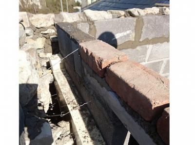
Site-formed cavity trays over lintels, openings or abutments
Cavity trays should be installed directly above the opening/lintel and be in a single continuous length (without joints) wherever possible. If joints cannot be avoided along their length, these should be rigidly supported and have a lap of at least 100mm, sealed according to material/product manufacturer’s details.
The tray must rise by a minimum of 150mm from the outer to the inner leaf of the wall, supported along its length to prevent it from sagging where possible (See Diagram 1).
The tray must be the full length of a lintel or width of abutment. They must have a stop-end at each end to prevent any moisture build-up dropping into the remainder of the cavity as illustrated in Diagram 1. Stop-ends need to be bonded to the cavity tray and well-sealed; achieving this with roll materials is likely to be difficult and the use of pre-formed stop ends bonded to the material in accordance with manufacturer’s details is recommended.

Diagram 1: Stop ends and cavity tray height
Likewise, because changes of direction of a cavity tray are more complicated than joints, involving complex bending and folding; it is recommended that prefabricated corner units are used, well-sealed to the cavity tray material (See example in Diagram 2).

Diagram 2: Prefabricated corner unit example
To allow water to drain out of the cavity, weepholes should be provided in the outer leaf immediately above the cavity tray and positioned at a maximum distance of 900mm centres. The tray should dress over any associated flashing or vertical membranes to ensure any water is drained outwards as illustrated in Diagram 3.

Diagram 3: Weepholes and lapping of trays
When a lintel runs continuously across narrow piers 600mm or less, it is recommended that a single cavity tray is installed across the pier.
It is important to remember that any laps must be well sealed and the cavity above the tray kept clean of any debris or mortar dropping to ensure adequate functioning.
For stepped abutments, it is recommended that site formed units are used, further guidance is contained within chapter 6.1.13 of the LABC Warranty Technical Manual.
Extensions and alterations
When an extension, new bay window or other relevant alteration is provided, the existing building should comply with all relevant requirements on completion of the works. It is likely that cavity trays will need to be provided above any new roof abutment to the wall. This will require masonry to be cut-out in suitable sections and cavity trays with stop-ends to be retrofitted adequately sat into both leaves of the wall. Weepholes, adequate sealing and pointing/joint interfaces will need to be carefully installed to ensure performance is maintained.
Installation will need to be undertaken in accordance with the principles discussed above and may require specialist input. Early discussion with the building control authority is recommended in this situation.
Cavity tray best practice
LABC Warranty provides further guidance in Chapter 6.1.13 of the technical manual and have provided the following best practice tips:
- Cavity trays should be installed over all external door and window openings including bay windows and at roof abutments, both horizontal and pitched.
- The cavity tray should be correctly located directly over the window/door head.
- Purpose-made stepped cavity trays are best utilised for all pitched roof abutments.
- Where natural stone/artificial stone heads are being used. It is advisable to double up the cavity trays, one below and one above the head and ensure that the cavity insulation continues to cover behind the stone head.
- Ensure weep holes are provided at each end of a horizontal cavity tray and at maximum 900mm centres.
- Ensure a weep hole is provided at the base of stepped cavity trays.
- Ensure the cavity trays are kept free of mortar droppings.
- Where using brick slip SIP panel lintels, cavity trays with stop ends and weep hole provision must be provided ‘above’ the SIP lintel, not behind it.
In addition, cavity trays and DPCs should be bedded into mortar below and provided above to prevent the potential for a slip or sliding. For DPC and cavity tray materials, always follow the manufacturers guidance and approved installation methods.
Please Note: Every care was taken to ensure the information was correct at the time of publication. Any written guidance provided does not replace the user’s professional judgement. It is the responsibility of the dutyholder or person carrying out the work to ensure compliance with relevant building regulations or applicable technical standards.
Sign up to the building bulletin newsletter
Over 48,000 construction professionals have already signed up for the LABC Building Bulletin.
Join them and receive useful tips, practical technical information and industry news by email once every 6 weeks.
Subscribe to the Building Bulletin
Related Content
How to use cavity wall ties correctly

Installing cavity wall ties in masonry walls

LABC quality management goes from strength to...
Comments
installing cavity trays
Submitted 4 years 4 months ago
LABC response
Submitted 4 years 4 months ago
The Building Control team at your Local Authority would be able to discuss any project specific requirements. You can find the contact details of the relevant Building Control team by entering your postcode in the search box at the top right-hand side of our website.
Best,
LABC team
Weep Holes
Submitted 4 years 4 months ago
LABC response
Submitted 4 years 4 months ago
Please contact the Building Control team at your Local Authority to discuss any project specific requirements. You can find the contact details of the relevant Building Control team by entering your postcode in the search box at the top right-hand side of our website.
Best,
LABC team
Heights
Submitted 3 years 11 months ago
Many thanks
LABC response
Submitted 3 years 11 months ago
Thank you for your recent enquiry regarding the positioning of Cavity Trays. This will very much depend on site specific conditions as well as the manufacturers instructions for both the tray and the lintel. We recommend that you discuss with the manufacturers, as well as with your local authority building control team, who will be better placed to inform you.
Best,
LABC team
Cavity trays at dpc level
Submitted 3 years 11 months ago
LABC response
Submitted 3 years 11 months ago
Thank you for your recent enquiry regarding the positioning of Cavity Trays.
This will very much depend on site specific conditions as well as the manufacturer’s instructions for both the tray and the wall construction proposed. We recommend that you discuss this with your local authority building control team, who will be better placed to inform you.
Best,
LABC team
Cavity tray on external blockwork that will be rendered?
Submitted 3 years 8 months ago
LABC response
Submitted 3 years 8 months ago
Thank you for your query.
Typically, weep holes are recommended in rendered walls. Rain driven moisture can enter the cavity through tiny cracks in the finish and this moisture should be allowed to dissipate.
Best,
LABC team
Add new comment