Separation of combustible material from masonry flues or fireplaces
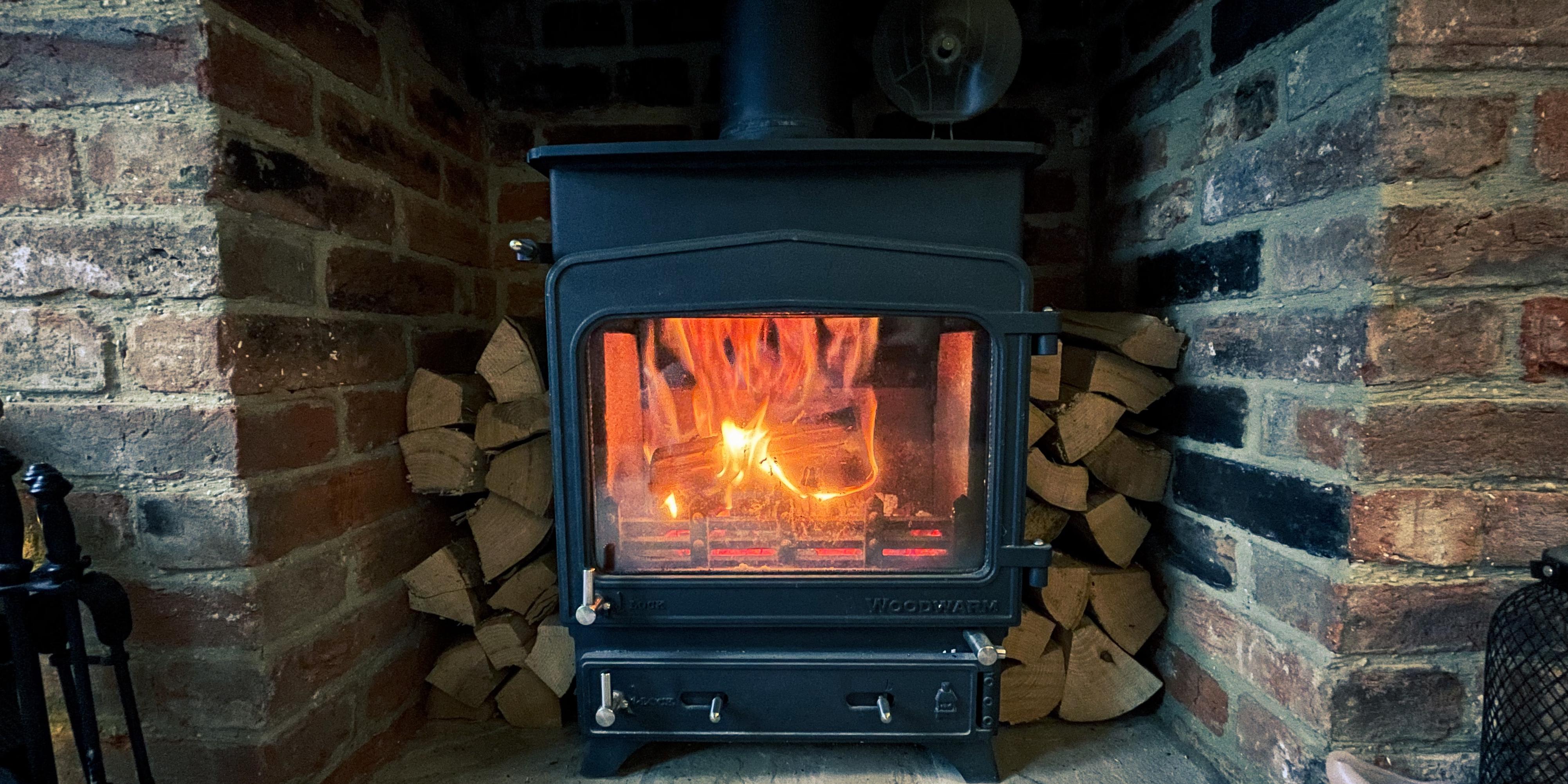
Heat through the walls of fireplaces or masonry flues can be transferred to other materials. This can lead to the possibility of fire in combustible materials that are close to the fireplace or flue and measures need to be taken to reduce this risk.
Approved Document J gives guidance on the positioning and minimum separation of combustible materials in or near chimneys used for solid fuel in paragraph 2.18 and diagram 21. Combustible materials would include floors, ceilings, trimmer joists and purlins for example amongst others. It is also important to consider thatch in relation to a chimney, further detail can be found in the LABC technical guide to thatched buildings (‘Dorset Model’).
The distance between a manufactured flue product and combustible materials should be in accordance with the stated flue designation; indicated by ‘Gxx’ where ‘xx’ is the distance in millimetres to combustible materials. In all cases, manufacturers declarations and documentation should be followed.
For all other situations, approved guidance confirms the minimum separation distance to be either:
- 200mm from the inside surface of a flue or fireplace recess as shown in diagram 1a below; or
- 40mm from the outer surface of the masonry chimney or fireplace recess as shown in diagram 1b below.
However, floorboards, skirting boards, dado/picture rails, mantel-shelves or architraves can be positioned directly against the masonry chimney in this situation. In addition, metal fixings in contact with combustible materials should be at least 50mm from the inside surface of a flue.

Diagram 1 – Separation distances of combustible materials from a flue (From ADJ Diagram 21)
In addition to the minimum combustible material separation distances given above, the minimum thickness of masonry chimneys must be the minimum distance ‘Gxx’ given in a manufacturer’s declaration. For other masonry chimney products, the minimum thickness of masonry chimneys as given in Diagram 20 of Approved Document J must be achieved as reproduced within diagram 2 below.

Diagram 2 – Minimum wall thicknesses for masonry and flueblock chimneys (ADJ Diagram 20)
For further information refer to Approved Document J for England or Wales.
Please Note: Every care was taken to ensure the information was correct at the time of publication. Any written guidance provided does not replace the user’s professional judgement. It is the responsibility of the dutyholder or person carrying out the work to ensure compliance with relevant building regulations or applicable technical standards.
Sign up to the building bulletin newsletter
Over 48,000 construction professionals have already signed up for the LABC Building Bulletin.
Join them and receive useful tips, practical technical information and industry news by email once every 6 weeks.
Subscribe to the Building Bulletin
Related Content
How to fix a stone fireplace surround -...

Chimneys and flues: Don't forget the...

LABC quality management goes from strength to...
Comments
Add new comment