How to get it right: Drainage of paved areas
One area commonly overlooked within building work is paved areas outside of the property. However since 2002 there has been a need to consider the adequate drainage of paved areas around buildings.
Requirement H3 of the Building Regulations 2010 in England imposes a requirement for paving, which provides access to buildings where M1, M2 or M4 (1), (2) or (3) imposes a requirement. This is in addition to access to solid waste storage H6 (2) or common passageways.
Requirement H3 in Wales imposes a similar requirement. However, there are subtle differences, namely as Requirement M4(1), (2) or (3) is currently not relevant in Wales.
Domestic buildings should be provided with a drainage system to remove surface water from paved surfaces, such as an access route that is suitable for disabled people, without endangering the building or the health and safety of people in and around the building caused through freezing.
The paved surface should be laid to ensure rainwater run-off is not close to the building.
Paved surface drainage systems should be designed, constructed and installed in accordance with the recommendations of Section 2 of the Approved Document Part H in England and Wales for areas up to 4,000m².
Free draining surface water run-off may be appropriate for small hard surface areas, such as access paths and driveways and can be achieved by laying the surface to a fall, sufficient to avoid ponding, that allows the water to drain to a pervious area, such as grassland, provided the infiltration capacity of the ground is not overloaded.
Also the discharge should not be adjacent to the building where it could damage the foundations.
The AD H Section 2 specifies examples of free draining surfaces, pervious paving and drainage systems appropriate for paved areas.
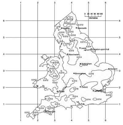
A designed rainfall intensity of 0.014 litres/ second/m² is assumed for normal situations, however, the recommendations of Diagram 2 in AD H may be followed to determine the regional rainfall intensity. An extract of Diagram 2 is below:
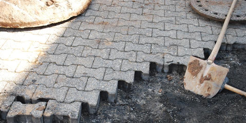
Most of the paving types will be free draining to a pervious area or constructed of pervious paving, however, if the paving is impermeable, i.e., water does not drain through them, but gathers on the surface such paving should be drained towards a disposal point, such as a gully or drainage grid and soakaway.
This would be the situation for small domestic paving projects where open gullies and grids are the most popular methods of paving drainage that connects to a soakaway.
Find this interesting? Browse our other 'How to get it right' articles
Example
How to calculate the drains capacity necessary for 95m² of paving
The calculation for drainage is based on the equation Q = (A x r) where:
- Q is the runoff capacity measured in litres per second
- A are the areas to be drained in m²
- r is the rainfall intensity in litres/second/m² . (ADH quotes 0.014 litres/second/m² for normal situations.)
So, Q = (A x r)
Q= 95 x 0.014 = 1.33 litres/second
So the drain should have a flow capacity of at least 1.33 litres/second.
Using Diagram 3 in AD H – it would appear that a 75mm diameter drain/channel laid at 1:200 gradient would be capable of handling this rainfall intensity. However, a 75mm diameter surface water drain serving more than one building would be unacceptable (as detailed in paragraph 3.14 of AD H). Furthermore 75mm and 100mm diameter drains and should be laid to a minimum of 1:100 gradient (as detailed in paragraph in 3.15 of AD H).
This runoff capacity needs to be taken into account if the drain connects into the surface water system If a soakaway is proposed then it needs to be able to handle the surface runoff and be able to disperse into the surrounding soil quickly enough for the soakaway to be able to cope with the next storm.
They are usually formed from square or circular pits, filled with rubble or constructed using attenuation crates wrapped in Terram geotextile membrane and externally backfilled with gravel and be a minimum of 5m from any buildings.
For small soakaways serving 25m² or less, a design rainfall of 10mm in five minutes may be assumed to give the worst case scenario as detailed in paragraph 3.27 of AD. However soakaways for larger areas should be designed in accordance with BS EN 752-4 or BRE Digest 365 and uses a percolation rate (how quickly rainwater infiltrates the ground) for design.
The final option is to use pervious paving but again the storage layer beneath the paving needs to be designed in the same way as soakaways to prevent retention and possible movement on sloping sites.
Further information
If you found this post useful, why not read some of our other articles about working with drainage:
- Level thresholds - landing and drainage
- Who is responsible for sustainable urban drainage (SuDS)?
- Building regulations guidance from LABC
Please Note: Every care was taken to ensure the information was correct at the time of publication. Any written guidance provided does not replace the user’s professional judgement. It is the responsibility of the dutyholder or person carrying out the work to ensure compliance with relevant building regulations or applicable technical standards.
This article was updated on August 2024
Sign up to the building bulletin newsletter
Over 48,000 construction professionals have already signed up for the LABC Building Bulletin.
Join them and receive useful tips, practical technical information and industry news by email once every 6 weeks.
Subscribe to the Building Bulletin


Comments
Draining of paved areas
Submitted 7 years 2 months ago
Failure to do so will most likely result in breaches of planning Law (or in the least leave clients at risk from this).
Also, the given rainfall rate is the bare minimum design rainfall rate and equates to 50.4mm/hr. This does not take into account any allowance for climate change, which currently stands at +40%. So all rainfall needs x 1.4 to include this.
Also, the type of sub-base, and it's thickness, can have a significant impact on the adequacy of pervious paving.
A min 350mm of DOT Type 3 (poorly graded with low fines) is a good starting point for up to 12 tonne road base capacity.
For far more detailed guidance that Part H can offer I'd suggest reference is made to the CIRIA SuDS manual.
Dr Rob Saunders
Sustainable drainage consultant
Drainage of new vehicular hardstandings
Submitted 7 years 2 months ago
Drainage of new vehicular hardstandings
Submitted 7 years 2 months ago
John
Add new comment